

 English
 中文简体
 Español
Industry News
Home / News / Industry News / Why In-House Mold Design Matters for Custom Rubber Part Quality and Lead Time

2026-10-26
A Tier 1 buyer sends an engineering change notice for a compression-molded rubber grommet: wall thickness up 0.3 mm, hardness target moved from 60 to 65 Shore A. If the supplier routes that revision to an outside tool shop, the buyer waits a week for a quote and two more for the modified tool. If the supplier designs and machines the mold in-house, the revision is normally quoted within 48 hours and first trial parts are on the bench in five days. That gap is why in-house mold design matters for custom rubber part quality and lead time.
For a custom rubber component, the mold is not a production detail; it is the product definition. Cavity geometry, shrinkage compensation, venting, flash grooves and parting line position decide whether the part seals, fits and survives its duty cycle. Jiaxing Tosun Rubber & Plastic Co., Ltd. (Tosun), a rubber manufacturer in Jiaxing with more than 250 employees, treats mold design as an in-house engineering function: 12 mold design and formula engineers work in the same building as material mixing, molding and extrusion, and a 20-person technical inspection team measures the results.
In-house mold design compresses a tooling iteration from weeks to days because drawing review, cavity machining and process feedback all happen under one roof.
Every design revision on a purchased tool follows the same slow route: the rubber molder forwards your change to an external tool shop, the shop re-quotes, fits the job into its schedule, machines the cavity, ships trial parts, and waits for feedback. Two or three cycles of this on a single program can erase an entire launch window. An in-house tooling team skips the quoting and scheduling steps completely.
The difference compounds across a program's life. Every PPAP round, material change and field fix hits the same loop. Tosun's custom molded hose program for OEM cooling systems stayed on schedule through a series of compounding revisions because each one moved directly from the formula engineer to the in-house tooling bench instead of across town.
The tolerance map of a compression-molded rubber part is fixed when the cavity is designed, not when the press closes.
Rubber shrinks after cure, and it does not shrink uniformly. Depending on polymer, filler loading and durometer, a typical EPDM or NBR compound moves 1.5-3.5% between cavity and cooled part. An external tool shop usually applies a book-value shrinkage factor to the customer drawing. When the material or the process shifts, that guess turns into dimensional rejects. An in-house designer applies shrinkage values measured on the actual compound, verifies the result on the first trial run, and corrects the cavity before production starts.
| Mold design decision | What it controls | Typical failure when outsourced |
| Cavity shrinkage allowance | Final outer and inner dimensions | Parts run oversize or undersize at PPAP; geometry rejected |
| Parting line and flash grooves | Flash thickness, trimming effort, seal surface | Tear marks and leak paths on gasket sealing lips |
| Vent placement | Air traps, knit lines, cavity fill | Voids at last-fill corners fail under pressure |
| Draft and ejection layout | Demolding stress and part distortion | Thin bellows walls stretch or split during stripping |
| Cavity steel and surface finish | Release behavior and surface texture | Sticking in production; surface defects on sealing faces |
Planning tolerance against a known process is what separates a rubber part that passes first-article inspection from one that needs three rounds of tool tweaks. A gasket with a 0.4 mm sealing lip, a bellows with a 1.2 mm wall, or a flange mount with bonded inserts all depend on the same thing: a cavity designed by the people who will run it.
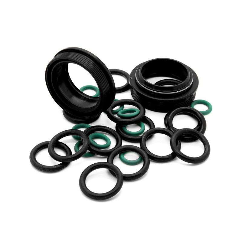
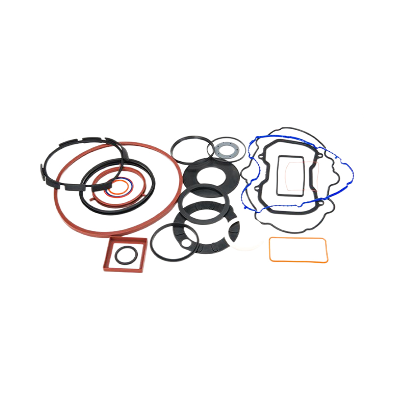 Flanged Rubber Gaskets and Seals for Dimensional Tolerance PlanningThis product page details flanged rubber gaskets across multiple compounds, supporting the paragraph's focus on cavity design and tolerance planning. Review material options and sealing applications to align compound behavior with predicted shrinkage and flow.View Product →
Mold geometry and rubber compound must be developed together because shrinkage, flow and bond behavior change whenever either side changes.
A hardness adjustment from 60 to 70 Shore A changes flow behavior and post-cure shrinkage. A switch from EPDM to a silicone blend changes draft angles, venting and release treatment. If compound development and mold design sit in different organizations, every material tweak triggers an expensive tooling re-cut. When the same engineers own both, the mold is designed against the actual cure curve and the formulation is adjusted to fill the cavity cleanly.
Shrinkage compensation is the practice of sizing the tool cavity larger than the target part dimension by the material's measured post-cure shrinkage, which for many EPDM and NBR compounds ranges from 1.5% to 3.5%. Done correctly, it converts a cavity dimension directly into an in-tolerance molded dimension.
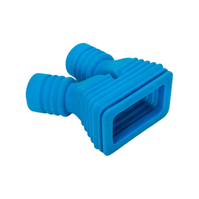
Complex parts make the interdependence visible. A rubber bellows with thin corrugated walls needs precise flow and demolding geometry; a fabric-reinforced diaphragm needs controlled deformation zones that line up with the cavity contour; a rubber-to-metal bonded mount needs bond-line placement matched to insert tolerances. Tosun pairs its 12 mold design and formula engineers on exactly these product groups, so a drawing change stays inside one feedback loop.
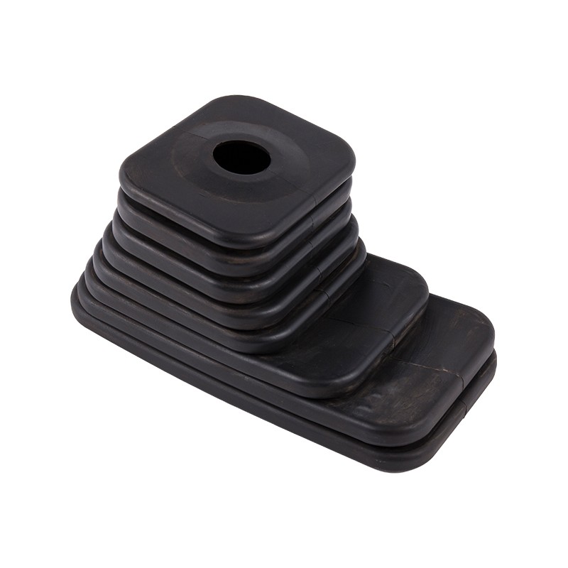
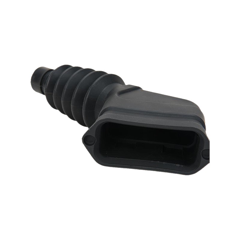 EPDM Gear Shifter Boot Bellows with Custom Mold DesignThe preceding text highlights thin corrugated walls and bond-line placement, and this bellows page specifies EPDM performance ranges and customization options. It demonstrates how in-house mold engineers handle complex demolding geometry for automotive applications.View Product →
You can verify in-house mold design capability with four direct questions, without requesting a factory tour.
The same audit applies to any supplier you evaluate. What a capable in-house shop demonstrates with numbers, an outsourced model usually cannot.
| Audit area | Evidence of real in-house capability | Red flag |
| Engineering team | Named mold design and formula engineers | We buy tooling from a partner shop |
| Machining | In-house CNC, EDM or wire-cut cavity work | All cavity machining subcontracted |
| Revision history | Dated records from change request to trial | No records; rework absorbed silently |
| First-article inspection | Same-day lab measurement and QC sign-off | Parts sent out for inspection after weeks |
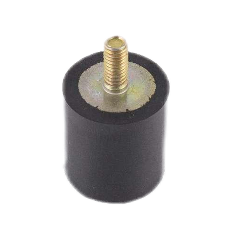
When a supplier passes all four checks, the purchasing decision shifts from price-per-tool to total lead time and first-pass quality across the program. The same standard applies whether the part is a flat gasket or a rubber-to-metal bonded mount; the bonded mount simply demands more from mold design, because insert position and bond crown live in the same cavity.
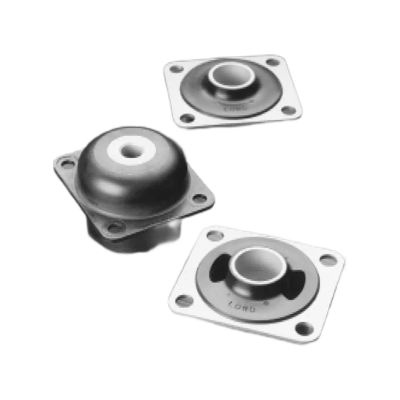 Rubber Vibration Isolation Mounts for Bonded Cavity DesignThis mount page lists EPDM, NBR, and customizable compounds with load capacity and vibration isolation details. It fits the discussion of rubber-to-metal bonded mounts, showing how insert position and bond crown are addressed in the cavity design.View Product →
On a typical custom program, initial tooling design is completed in 2-4 weeks in-house versus 6-10 weeks through an external tool shop. For revisions during PPAP or after field failures, the gap is 3-5 days versus 2-4 weeks per loop.
Not by itself. Tighter tolerances come from designing the cavity against the actual compound's shrinkage and flow, then measuring first articles with the same team. In-house mold design creates the conditions for that loop; it does not guarantee the result on its own.
Yes. Even a flat gasket depends on shrinkage compensation, flash groove placement and parting line location. Simpler parts also have the smallest engineering margin, so an inaccurate cavity shows up as rejects within the first production run.
Ask the four audit questions: engineer headcount split, cavity machining location, revision records, and first-article response time. A supplier with real in-house capabilities will answer all four with names, dates and measured results.
Contact Us
Copyright ©
Jiaxing Tosun Rubber&Plastic Co., Ltd.
All Rights Reserved.
Custom Rubber And Plastics Products Factory