

 English
  中文简体
中文简体  Español
Industry News
Home / News / Industry News / Flexible Rubber Bellows, Custom & Industrial Bellows and Crushproof Tubing Guide

2026-04-02
Flexible rubber bellows are accordion-pleated or convoluted elastomeric components designed to accommodate axial compression, extension, lateral offset, and angular misalignment between connected assemblies while maintaining a sealed enclosure. The corrugated wall geometry is not decorative — each convolution acts as a flexible hinge point that distributes mechanical strain across multiple folds rather than concentrating it at a single bend. This distributed flexing allows bellows to undergo millions of compression-extension cycles without fatigue cracking, provided the correct material and convolution geometry are specified for the displacement range and load conditions.
The sealing function is equally important. Bellows enclose linkages, shafts, joints, and cables to exclude contaminants — dust, grit, moisture, chemicals, and biological matter — that would accelerate wear or cause corrosion on the protected components. A CV joint boot on an automotive driveshaft is perhaps the most widely recognized example: the bellows retains lubricating grease at the joint while blocking road debris and water. When this boot splits or tears, grit enters within days and the joint fails within weeks — the bellow's role is not structural but protective, and its failure is disproportionately consequential.
The distinction between rubber bellows and metal bellows is worth establishing clearly. Metal bellows — typically formed from thin stainless steel or bronze — offer higher temperature resistance, precise spring rates, and vacuum service capability, but have limited lateral deflection capacity and fatigue life under large-amplitude vibration. Flexible rubber bellows accommodate larger multi-axis displacements, absorb vibration rather than transmitting it, and tolerate higher misalignment without generating reaction forces that load the connected equipment — advantages that make rubber the dominant choice in most mobile machinery, general industrial, and fluid handling applications.
Industrial rubber bellows are manufactured from a range of elastomer compounds, each suited to different combinations of temperature, chemical exposure, pressure, and dynamic load. Compound selection is the single most consequential engineering decision in bellows specification — a bellows with correct geometry but wrong material will fail prematurely regardless of wall thickness or convolution count.
| Compound | Temp Range | Oil Resistance | Ozone / Weather | Typical Use |
|---|---|---|---|---|
| Natural Rubber | -50°C to +80°C | Poor | Poor | High-cycle dynamic bellows |
| Neoprene (CR) | -40°C to +100°C | Moderate | Good | Outdoor, HVAC, marine |
| EPDM | -40°C to +150°C | Poor | Excellent | Steam, hot water, automotive cooling |
| Nitrile (NBR) | -40°C to +120°C | Excellent | Poor | Hydraulics, machine tools, fuel |
| Silicone | -60°C to +200°C | Moderate | Excellent | Aerospace, food, high-temp |
Off-the-shelf bellows cover a wide range of standard bore diameters and stroke lengths, but many industrial applications require custom rubber bellows due to non-standard bore sizes, unusual stroke-to-diameter ratios, end fitting configurations, or chemical resistance requirements that no stock product addresses. Custom bellows are tooled and molded to order, with lead times typically ranging from 4–12 weeks for compression molded designs and 6–16 weeks for transfer or injection molded configurations depending on tooling complexity.
The geometric parameters that define a bellows and must be specified for custom production are:
Crushproof tubing is a bellows-geometry tube designed to resist radial collapse under external compressive load — from vehicle tires running over cable runs, equipment being dragged across the tube, or heavy foot traffic — while remaining flexible enough to route around corners and accommodate vibration. The corrugated wall provides resistance to crushing by distributing the compressive force across multiple convolution walls acting in compression rather than allowing a smooth tube wall to buckle inward at the point of load application. Crushproof tubing is used extensively for cable and hose protection in factory floors, outdoor cable management, vehicle underbody routing, and agricultural machinery where exposure to physical impact and abrasion is unavoidable.
Material selection for crushproof tubing parallels general industrial rubber bellows selection, with the addition that UV stabilization and abrasion resistance are typically prioritized since these tubes spend their service life exposed to surface contact and outdoor conditions. Polypropylene and polyamide crushproof tubing competes with rubber variants in many cable protection applications, offering higher crush load resistance and lower cost at the expense of flexibility at low temperatures and impact resistance in cold climates.
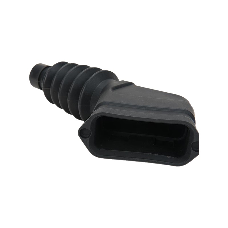
A bellows rubber boot is a convoluted rubber enclosure — typically tapered or cylindrical — used to protect a specific mechanical joint, bearing, or actuator from contamination while accommodating its range of motion. Rubber boots differ from general-purpose bellows primarily in their attachment geometry: one end is typically sized to clamp tightly around a fixed housing or collar, and the other end clamps around a moving shaft or rod, with the convolutions in between accommodating the relative motion between the two. Common examples include steering rack boots, ball joint boots, tie rod boots, and shift lever boots in automotive applications, as well as linear actuator boots and cylinder rod boots in industrial machinery.
Boot failure mode analysis is instructive for specifying replacements. Most rubber boot failures fall into three categories: ozone cracking (surface cracks perpendicular to stress, caused by ozone attack on unsaturated rubber — indicates a compound switch to CR or EPDM is needed); fatigue cracking at convolution roots (caused by operating beyond the designed stroke range or at too high a cycle frequency — indicates geometry redesign or stroke limitation); and clamp-point tearing (caused by inadequate end wall thickness or improper clamp torque — indicates end geometry or installation procedure correction). Identifying the failure mode before ordering a replacement boot prevents the same failure from recurring on the new part.
Contact Us
Copyright ©
Jiaxing Tosun Rubber&Plastic Co., Ltd.
All Rights Reserved.
Custom Rubber And Plastics Products Factory


